23 December 2019 |by Léon van Berlo – buildingSMART International
Link to Original Article: HERE
The buildingSMART lingo consists of many abbreviations. Some more commonly used than others (does anyone still use IFD?). But one of the most confusing acronyms is “MVD”. The abbreviation MVD stands for ‘Model View Definition’, but knowing what the acronym is, does not necessarily mean it’s fully understood.
What are MVDs really?
As many people know, IFC is a large and wide set of definitions, relations and properties about entities. These agreements define a wall (IfcWall) but also sensors (IfcSensor) and little known entities like IfcCondition (determines the state or condition of an element at a particular point in time), IfcMove (an activity that moves people, groups within an organization or complete organizations together with their associated furniture and equipment from one place to another) and IfcPermit (a document that records permission to carry out actions in places and on artifacts where security or other access restrictions apply). This makes it much more than just a syntax or file format.
This rich set of agreements is often too much for a software developer to implement in full into their software tool. There are many different domains and workflows represented that are far broader than the deliberate focus many tools and platforms are developed to address. Thus, it does not make sense to require vendors to implement the entire scope of the schema because no single software tool requires all of the data types that IFC defines.
Model View Definitions have been created to deal with this situation. In general, everyone seems to agree that it is a selection of entities from the full IFC schema definition. Over the years there was a subtle change in the definition. The term ‘use-case’ was introduced. These days you can also find definitions of an MVD that refers to a “standardized exchange of data for a specific use-case”.
Today there are three levels/layers of definitions:
- The schema itself (represented in figure 1 as the blue outer line);
- The Model View Definition, a subset of the full schema (represented in figure 1 as the green circle);
- The use-case specific information requirements, usually part of an MVD that is implemented in software (represented in figure 1 as the orange box).
The MVDs are not only a subset of the full schema, but usually also have additional constraints and requirements. The information requirements tend to be a selection of entities from an MVD to be sure users can import and export that Exchange Information Requirement (EIR) in their software, but this can also be extended with additional classifications and properties outside of the MVD, or even outside IFC.
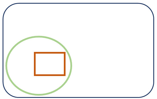
Figure 1: The schema (blue), subset MVD (green) and information requirements (orange)
Up to IFC 2×3, MVDs have been very closely related to the full schema. The MVDs defined different ‘conformance levels’ in the software. This is also the reason why the MVDs are the base for the software certification.
With the increased need for extending the IFC schema, and companioning MVDs, the overlap between MVDs and software implementation conformance levels is loosening, and there is a mix-up between MVDs and exchange information requirements.
There are currently two ‘official’ MVDs in IFC4 (Reference View, and the upcoming Design Transfer View). An additional 5 are being worked on (Precast, Quantity Takeoff View, Energy Analysis View, Product Library View and Construction Operations Building Information Exchange). That means we have 7 different certification procedures. When a user receives an IFC dataset (a file), the user has to check which MVD the file covers, and check if their software tools are certified against that MVD.
With the expansion of IFC into road, rail, bridge, tunnel, landscape, etc. the current procedure is to define different MVDs for those extensions as well. All of these extensions have 2 or 3 additional MVDs. This brings the total number of MVDs in the next release to almost 20.
That means 20 different dialects of IFC. Twenty different implementations in software. When this continues the number of MVDs will reach hundred before we realize it.
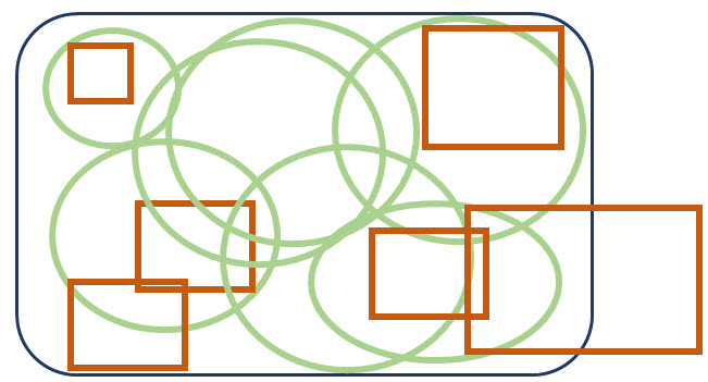
Figure 2: the expansion of MVDs and EIRs adding data from outside an MVD and the IFC schema
Future proof MVDs
There are a couple of reasons why the above approach is not sustainable in the future.
1. User expectations
Staying on the current MVD track, would mean we are going towards a procedure where every use-case (MVD) needs a formal approval process of several years, a bespoke implementation process, a separate certification procedure, to end up in a situation where an ifc file is exchanged between users that have no guarantee that they can import that file into their tool without the right checking process to see which dialect is from the 100 or so potentials.
As a community we have been explaining to outsiders that ‘there is no one IFC’ and you have to look at the MVD. But we know that users have other expectations – and rightly so.
2. Dynamic exchange information requirements
There are more and more examples of Exchange Information Requirements that define entities from IFC without looking at MVDs and adding additional requirements for classifications and properties. The ISO19650 definition of Exchange Information Requirements (EIR) is much more dynamic and is based on the Project Information Requirements.
Currently there is a mix-up between the formally defined MVDs, and the dynamically defined EIRs. You could see standardized formal EIRs as MVDs. But sticking to MVDs as the base for implementation and certification is not sustainable to support the dynamic EIRs the industry so desperately needs.
3. Interoperability
IFC is more than just an exchange format between software tools, and with the rise of digital twins and Common Data Environments (CDE) you cannot ask those CDE developers to implement a hundred (or even 20) separate subsets of IFC.
There is a danger that extensions add bespoke entities that are only used in one or two use-case specific MVDs. Different geometry types can be defined and used in different MVDs. When this happens the differences between MVDs (and therefore IFC implementations) will grow. We will end up with different MVDs that are not interoperable with each other.
4. Maintainability
The current extensions are working together in the ‘IFC Infra Extensions’. The harmonization of entities between different extensions is discussed until there is one single harmonized IFC, and then sliced up in the almost 20 MVDs. Harmonizing the full set of IFC definitions will become harder and harder when the schema keeps expanding. Every new extension needs harmonization with the existing entities. This makes all existing extensions responsible for any new addition. The maintainability of this approach does not scale. With an increasing demand to speed up IFC release cycles, this approach of creating a full harmonized schema first and slicing it up afterwards is unsustainable.
Modularization as a possible solution
To tackle these issues, there is a growing call for an increased modularization of the IFC schema, and a reconsideration of MVDs as the basis for certification.
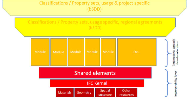
Just like any other major standard, IFC should define a shared base. This has always been in place with the ‘interoperability layer’, and the specialization structure of IFC makes it possible to have dynamic (‘late binding’) extensions.
Modularization of the schema makes it easier to separate responsibilities, and distribute maintainability of the entities, and possibly even have separate release cycles per extension. This would solve the issue about maintainability of the schema as mentioned in point 4.
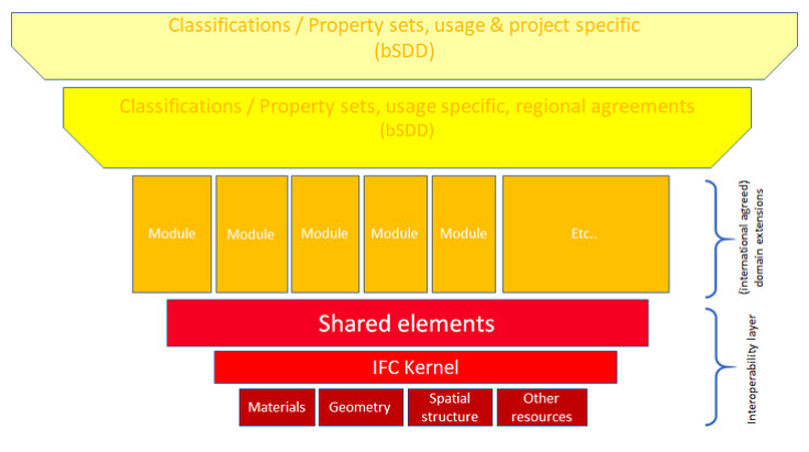
Figure 3: extensions on a shared base creates interoperability
When the extensions use the shared base (the red part in Figure 3), they would be required to extend from the entities of that shared base, by default providing interoperability between domains. It is a challenge to make this shared base as lean and strict as possible, but also holding enough richness to facilitate all the extensions. A lean and strict base would mean that implementors of IFC would by default have to implement the full set of the shared base. This would create the de-facto interoperability between implementations and solve issue 3. There are big challenges here since the current resource layer (mainly geometry) needs a cleanup, and it is difficult to define a border between the shared layer and extensions. The provides big challenges, but for a good cause.
As mentioned before, MVDs not only define a subset of the entities in IFC, but also an implementation conformance level. The two or three different MVDs per infra extension are in that sense almost the same – they define a simple geometry conformance, an advanced one, and an advanced one supporting the retention of parametric information after import. This can be compared with the Reference View (simple geometry), the ‘former’ Coordination View (advanced geometry), and the Design Transfer View (retaining parametric information after import).
- Standardizing these conformance levels for the shared base, would make them available in the same way for every extension, also contributing again to increase interoperability in implementations.
When the shared base is implemented, the extensions are basically an additional specialization of classification and properties. Implementation of the extensions therefore (ideally) might be late binding. This would mean that the support of multiple extensions would be a lot easier compared to implementing a new MVD every time. The time between the publication of a new version of an IFC extension, and the availability in software would also decrease drastically.
The impact on certification would be quite significant. The different conformance levels of implementation of the shared base would be natural certification levels. It would make sense to also have certification of the extensions to provide guarantee to users that the mapping of the internal vendor data model to IFC (and the other way around) is done correctly. For users, the standardized conformance levels for certification would mean much more clarity about the ability to open or import a file, solving issue 1 (to some extent).
- The difference between early binding implementation of the shared base (red layer in figure 3), and late binding of the extensions, also paves the way for supporting dynamic Exchange Information Requirements (EIRs) from ISO19650.
There can of course still be standard exchange information requirements for use-cases like facility management and fabrication. Those standardized use-cases will share the same basis and are by default therefore interoperable with each other. They will have their own maintenance team and release cycle. The IFC certification will be on a different level, and software that is certified for IFC provides users the guarantee that they can also import and export these standardized exchange information requirements.
As you see, many of the issues are entangled and related to each other. With the move to UML/XMI as the main structure to maintain IFC, a new world opens to formally define extensions and Exchange Information Requirements. The current way of defining an exchange requirement is limited. We should rethink this technology to create the ability to also add classifications and properties from bSDD, and even project- and user-specific properties from outside bSDD and IFC.
The case of the MVDs might appear curious, mainly because the term is used for different things. Untangling the terminology, and communicating clearly about the difference between subsets of IFC for software implementations and Exchange Information Requirements makes it more digestible. There are huge opportunities when we use MVDs as it was originally intended.
Creating a future proof IFC, with better implementations and the ability to validate machine readable dynamic exchange information requirements, is a big challenge. We need to make the interoperability layer stricter, and we need to clean up entities that are rarely used (and are only in there for a specific purpose).
Some of the challenges and questions are presented in these slides: https://www.slideshare.net/secret/NrtaQe2E6BLUL
Feel free to send us feedback and suggestions on leon.vanberlo@buildingsmart.org